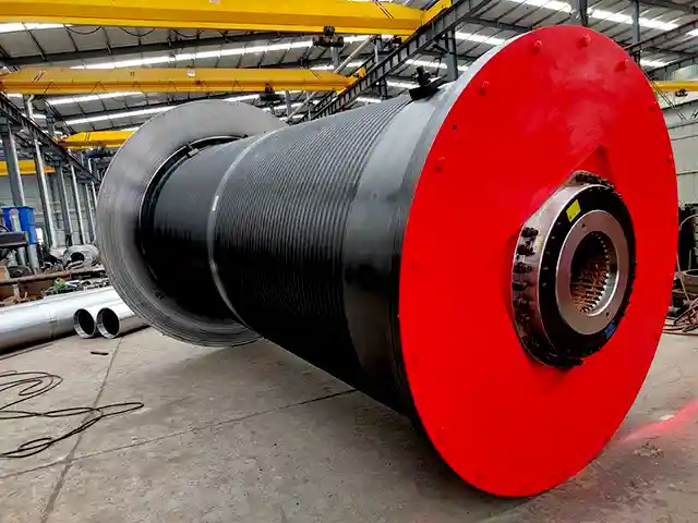
Crane drums are the primary load-bearing components of the hoisting system. Driven by a motor, the drum reels and unreels wire rope to actuate the block-and-hook assembly and lifting gear; drum performance therefore directly determines crane safety and operational reliability.
Material selection must balance strength, wear resistance and impact toughness. Cast steel (for example, grades such as ZG35SiMn) is widely used for heavy-duty applications due to its balanced properties; welded drums are commonly fabricated from high-strength plates such as Q345B and are favored where weight reduction is required.
In corrosive or marine environments, stainless steel variants may be selected to improve corrosion resistance. This guide, aligned with national standards (for example, TSG Q0002-2008 — Technical Supervision Regulations for Hoisting Machinery Safety and GB/T 5031-2019 — Tower Cranes), systematically summarizes drum types, structure and safe-use requirements.
Premium Custom-Made Crane Drums Available | Explore Our Offerings!
Classification of Crane Drums and Typical Applications
Drum classification should consider manufacturing method, structural form and operational requirements. Different types vary significantly in performance, cost and appropriate applications. Key classifications follow.
By manufacturing process
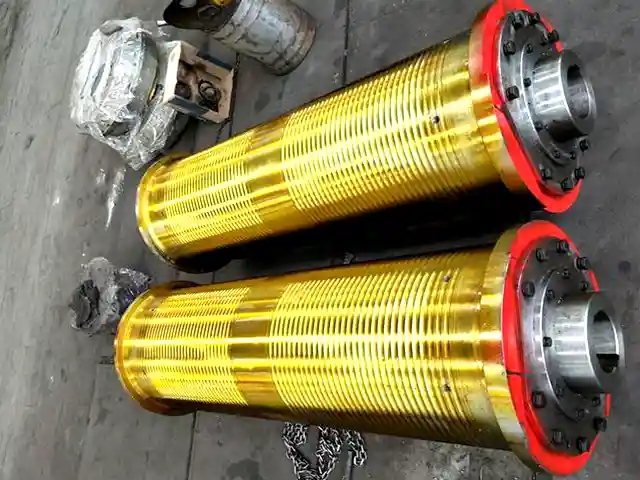
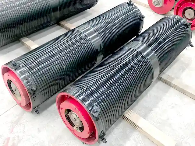
Cast drums — Produced by sand casting or centrifugal casting. Cast drums have an integral, dense structure and good impact toughness, making them suitable for heavy, high-frequency applications such as metallurgy and mining. Drawbacks include longer production cycles, greater mass, and potential casting defects (porosity, sand inclusions). Non-destructive testing (NDT) is required to verify quality.
Welded drums — Fabricated from rolled plate and welded into shape; welds must be inspected for defects. Advantages include lower weight, shorter lead time and higher material utilization. Welded drums suit medium- and light-duty service such as bridge and gantry cranes. For large tonnages, a “rolled shell + welded flange” composite design can increase load capacity.
By structural features
By shaft/support arrangement
Long-shaft drums: Supported at both ends by bearing housings; provide higher shaft rigidity and are suited to large-diameter or long barrels (common on house-type/portal cranes).
Short-shaft (cantilever) drums: Cantilever-supported from one side; compact and space-saving—typical for small bridge cranes and electric hoists.
By rope-groove/surface form
Grooved (helical) drums: The barrel is machined with helical, arc-section grooves that ensure orderly single-layer rope lay, reduce inter-strand friction and extend wire-rope life. Preferred for single-layer winding.
Plain (smooth) drums: No preformed grooves; typically used for multi-layer winding. Disadvantages include greater stacking wear on the rope; a rope-laying (level-wind) device is usually required to ensure orderly layering.
By number of winding layers
Single-layer drums: Use helical grooves to guide a single rope layer; provide stable operation and are common across general cranes.
Multi-layer drums: Used where large lifting heights or limited installation space require multiple layers (for example, tower cranes). Layer count should be controlled (commonly ≤ 3 layers), and rope arrangement must be inspected regularly.
By drive type (cable/reel drums)
Cable drums used for power and signal management are categorized by drive:
Non-motorized
Spring/tension type (TA series): Suitable for short travel (≈ ≤ 30 m), e.g., electromagnetic lifters.
Gravity/weight tension (ZC series): Suitable to ≈ 50 m travel—used in heavy-duty metallurgy vehicles; stable performance.
Magnetic coupling (JQC series): Can support >100 m travel but requires synchronized cable-guiding devices.
Motorized
Torque-motor type (KDO series): Suitable for large-section cables up to ≈ 800 m travel; used on gantry cranes.
Variable-frequency tension control (BP series): Closed-loop torque control provides constant tension and can meet complex conditions beyond ≈ 1,000 m (e.g., container quay cranes).
Core Structural Components and Their Functions
A drum comprises four primary components — barrel (drum shell), hub/connection plate (flange), drum shaft, and bearing housings — plus optional auxiliaries such as flanges and rope-laying devices. Key functions and design considerations follow.
Barrel (drum shell): The winding surface for the wire rope. For grooved drums, groove pitch should match wire-rope diameter (groove pitch = wire-rope diameter × 1.05–1.10). Plain drums must have flanges at both ends to prevent rope run-off. Barrel wall thickness is derived from rated load calculations; heavy-duty drums commonly use variable wall thickness designs to optimize strength and weight.
Hub / connection plate (flange): Connects barrel to shaft and transmits motor torque. Typically a flange-welded structure; large drums require stiffening ribs to improve torsional stiffness. Mating surface flatness should meet tolerances (for example ≤ 0.1 mm/m) consistent with GB/T 1184 where applicable.
Drum shaft: Carries radial loads and torque. Commonly manufactured from quenched-and-tempered 45 steel; journal areas are often induction hardened to improve wear resistance. Shaft-to-bearing housing fits should meet tolerance classes such as H7/js6 to ensure stable rotation.
Bearing housings: Support the shaft assembly and are typically cast iron or welded plate structures. They must be rigidly fastened to the frame with foundation bolts; base shims should be provided to level and align the shaft.
Safety Regulations for Use: Inspection, Operation, Maintenance, Retirement
Safe drum management must cover the full lifecycle — inspection, operation, maintenance and retirement — and comply with applicable standards (for example TSG Q0002-2008, GB/T 5031-2019).
Daily and periodic inspections
Daily (pre-shift): Visually inspect the barrel for cracks or deformation; check grooves for pitting or dents; verify orderly rope lay — if cross-lapping or crushing occurs, rectify immediately. Check the wire-rope end-termination (clamp, wedge, etc.) for tightness and signs of loosening.
Monthly: Verify anti-loosening performance of end-termination hardware — measure bolt torque with a torque wrench per design requirements (commonly ≥ 80 N·m). Measure groove wear; if wear exceeds 1/4 of the wire-rope diameter and cannot be restored by turning/lathe rework, mark for replacement.
Annual: Engage a qualified third-party for NDT (ultrasonic testing of barrel and flange welds; magnetic-particle inspection of the shaft). Measure barrel wall wear, record the wear distribution and issue a formal inspection report.
Operational safety essentials
Safety wraps: Maintain sufficient safety wraps on the drum. When the hook is at the lowest position, at least three (3) wraps must remain on the drum. When the rope is fully paid out, at least five (5) wraps must remain. Wraps must be tight and not suspended.
Flange height (single-layer drums): When the rope is fully reeled in, flange height should exceed twice the outer rope diameter to prevent run-off. For multi-layer drums flange height should be increased (commonly 3–4 times the rope diameter).
Overload and shock avoidance: Operating load must not exceed 110% of rated capacity. Sudden starts/stops that cause rope impact loading are prohibited. If abnormal drum noise or vibration occurs, stop the machine immediately for inspection and remediation before resuming work.
Retirement (scrapping) criteria
A drum must be scrapped immediately (no downgraded reuse) if any of the following conditions occur:
Any visible crack in the barrel, flange or shaft, or internal fatigue cracks detected by NDT.
Barrel wall wear reaches the scrapping threshold: for general cranes, wear ≥ 20% of original wall thickness; for tower cranes, wear ≥ 10% of original thickness. For uneven wear, use the maximum local wear measurement.
Severe groove wear or deformation: groove bottom diameter reduced by more than 50% of the wire-rope diameter, or groove side-wall wear causing distortion that prevents orderly rope laying.
Drum shaft plastic deformation or excessive bearing seat wear leading to loss of rotational accuracy (radial run-out > 0.2 mm/m).
Maintenance and preservation actions
Regularly lubricate drum shaft bearings; grease fill should be approximately 1/2–2/3 of the bearing cavity. Use a lithium-based grease suitable for −20 °C to 80 °C service where applicable.
For outdoor drums, clean dust and debris regularly and perform anti-corrosion treatment at least every six months (touch-up primer and finish paint).
For cable (power) drums, inspect drive-train tension. Variable-frequency tension control systems should be periodically calibrated to ensure reel speed remains synchronized with crane motion.
Conclusion
Manage crane drums under a “prevention-first, full-process control” regime: select drum type to match operating conditions, perform standardized inspections to identify hazards early, enforce safe operating procedures to mitigate risk, and retire drums promptly when retirement criteria are met.
Operating units should establish drum-specific management procedures and provide pre-shift training so that operators understand drum structure and safety requirements. These measures together ensure safe, reliable crane operation and help extend component service life.
Contact us for high quality crane drums and other crane related products!